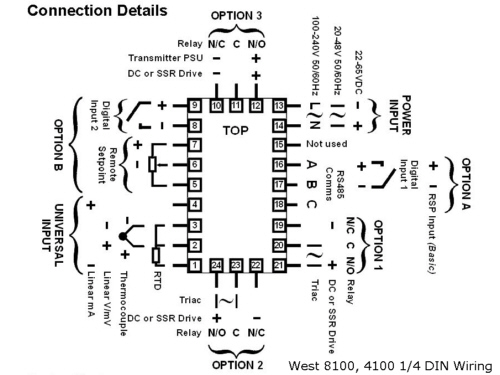
Below is based on connecting to a West 8100, 4100 4400 control. The information is applicable to other controls although the terminal numbers will likely be different.

2 Wire Probes
It is possible to use a 2-wire PT100 probe with this instrument. Connect the 2 wires from the probe to terminals 2 & 1. Place a wire link from terminal 2 to terminal 3. This simulates a 3-wire probe, and will indicate the correct value for probes with short leads. It should be remembered that 2-wire probes do not allow the instrument to compensate for the resistance of the leads. This can cause high readings when long leads are used. If this is the case, replace the 2-wire probe with a 3-wire type.
Using 4-wire probes
There are two types of 4-wire probe, shunt types which have two wires attached each side of the sensor element, and classic compensated types with a single wire attached to each side of the sensor element and a separate loop of wire to compensate for the length of the lead. It is possible to use either type of 4-wire probe with this instrument.
Shunt Types
Establish which wires are attached to each end of the sensor element using a resistance meter. A reading of approximately 100 to 110 ohms (at room temperature) between any two wires means that they are from different sides of the element. A reading of approximately zero indicates that the two wires are connected to the same side of the element. Connect the two wires from one side of the element, to terminals 2 & 3. Connect one of the wires from the other side of the element to terminal 1. DO NOT CONNECT THE 4th WIRE. This should be cut short or tied back so that it cannot contact any of the rear terminals on the unit. This uses your 4-wire probe as a 3-wire probe, and will indicate the correct temperature.
Classic Types
Establish which wires are attached to the sensor element using a resistance meter. A reading of approximately 100 to 110 ohms (at room temperature) between any two wires means that they are connected to the element. A reading of approximately zero indicates that the two wires form the compensation loop. If the reading is open circuit then one wire is from the element, while the other is from the compensation loop. Connect the two wires from the element, to terminals 2 & 1. Place a wire link from terminal 2 to terminal 3. DO NOT CONNECT THE COMPENSATING LOOP WIRES. These should be cut short or tied back so that they cannot contact any of the rear terminals on the unit. Using this loop as the link between terminals 2 & 3 will cause the instrument to over compensate for the length of lead. This uses your 4-wire probe as a 2-wire probe. The link from 2 to 3 simulates a 3-wire probe, and will indicate the correct value for probes with short leads. It should be remembered that 2-wire probes do not allow the instrument to compensate for the resistance of the leads. This can cause high readings if long lead lengths are used. If this is the case, replace the 4-wire probe with a 3-wire type.
