
4100, 6100 & 8100 Series Controls
In order to communicate with West controllers you will need the following hardware. Also below are the common configuration settings for the controls.
Hardware
1) A communication board must be installed in each control that will be connected to the computer. For newer series West single loop controls (6100, 4100, 8100, 4400 etc) the part number is N9610-X06. This option board when properly installed and configured in the control provides RS485 communications.
2) 1 each RS485 to RS232 Converter & RS232 serial cable (P/N IC108A) or 1 RS485 communication port on the computer in which Commander is to be installed. You will need one converter or port for every 32 devices to be connected to the computer.
3) Connect the RS485 connections between the converter or RS485 port on the computer and the instruments to be monitored. Up to 32 devices can be connected on the same pair of communications wires. Use shielded twisted pair wire with the shield connected to earth ground at one end only.
Instrument Configuration
Check that communications is configured & set baud rate and address.
The following is based on 4100, 6100 & 8100 series controllers: (Other west controls are setup similarly, follow the instructions in the manual) Note: Caution must be exercised in this mode. Misconfiguration of other parameters in this mode can cause inaccurate readings, possible loss of control and damage to process.
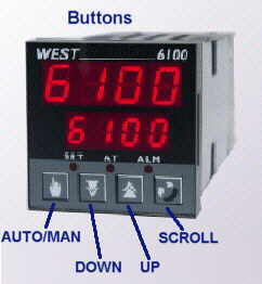
1) Enter the configuration mode by turning off power to the control then reapply powerl. While it is powering up Press and hold the both the Scroll and the UP keys at the same time. Hold until inPt is displayed in the lower display.
2) Momentarily press both the Down and the Scroll buttons at the same time. dEFn will be displayed in the lower display.
3) Press Scroll key. Optn will be displayed in the lower display. Use the Up or Down buttons to display r485 in the upper display. Press Auto/Manual (Hand key) to enter the value. Note: Communications board is required to be installed in the control for communications to work. See previous section for hardware requirements.
4) Momentarily press the Down & Scroll keys at the same time. You should be back at the inPt display.
5) Press the Scroll key until bAud is displayed in the lower display. Set the baud rate to the desired value. Normally 9600 is recommended. Commander software baud rate will have to be set to the same value. All instruments on the same communication port must have the same baud rate. Press Auto/Manual (Hand key) to enter the value.
6) Press the Scroll key until Addr is displayed. Set the address as required to a number between 1 & 32. Each instrument must have a unique address. Normally the addresses should be set sequentially ie: 1, 2, 3, 4... Press Auto/Manual (Hand key) to enter the value.
7) Press Up and Scroll buttons together and release to exit the configuration mode.
The instruments hardware and configuration are now set to communicate with a software package such as ISE's Commander Software. See software documentation for software setup.